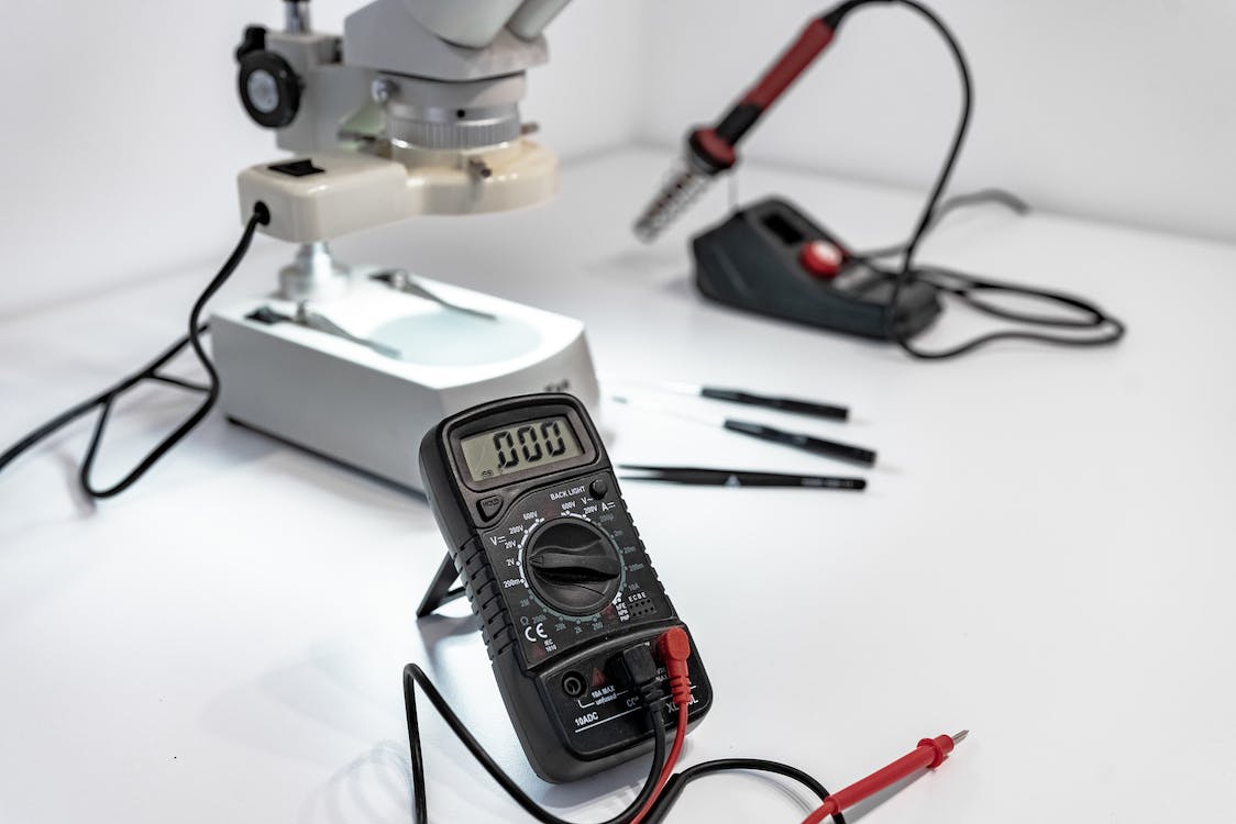
Electronic devices often encounter hidden problems that aren’t visible to the naked eye. Issues like damaged circuits, shorts, or disconnected components can render a device dysfunctional. However, by utilizing the continuity test function on a multimeter, you can easily determine whether a circuit is open or closed, and if the current is flowing properly. In this guide, we will explore the concept of continuity, explain how the continuity test works, and provide step-by-step instructions on how to conduct a continuity test using a multimeter.
Understanding Continuity
Electricity requires uninterrupted pathways to flow between various parts of a circuit. When a disruption occurs within the electrical flow, it can lead to malfunctioning devices. Conducting a continuity test helps identify if an electrical pathway is open or closed, allowing current to flow smoothly between each point.
Purpose of the Continuity Test
The continuity test is designed to verify the continuity of electrical flow within a device or wire. By examining whether each part of the circuit is connected in a closed loop, this test determines if there is a continuous pathway for the current to follow. Most multimeters emit a beep or display an alert when a closed-loop and operational continuity are detected. However, models without a built-in continuity test can still measure resistance, albeit without providing an audible indication of continuity.
How Does the Continuity Test Work?
When the probes of a multimeter make contact with two points, a small current is sent into the circuit. The multimeter then measures the resistance within the circuit and provides feedback on its operational status. Depending on the multimeter model, it may emit a beep or display a numerical value to indicate continuity. Referring to the user manual is crucial to interpret the multimeter’s readings accurately.
Safety Measures for Conducting a Continuity Test
Before proceeding with a continuity test, it is vital to ensure safety:
- Disconnect the device or component from any power source.
- If working with household devices connected to fuses, turn off the primary power source for the house.
- Avoid performing continuity tests on devices powered from alternative sources.
Identifying the Continuity Test Symbol on the Multimeter
The symbol representing the continuity test can vary depending on the multimeter model. Look for a diode symbol or a wave symbol, typically indicated in the multimeter’s manual.
Step-by-Step Guide: Testing Continuity With a Multimeter
Follow these general steps to perform a continuity test using a multimeter:
- Disconnect the device or component from any power source.
- Insert the left probe into the designated port on the multimeter.
- Insert the right probe into the corresponding port on the multimeter.
- Turn on the multimeter and set the dial to the Ohms or Continuity Test setting.
- Adjust the range on the multimeter according to the resistance you are testing for, using the lowest possible resistance setting for components with low-resistance values.
- Select the continuity test function on the multimeter using the appropriate dial setting.
- Touch the two probes together and listen for a beep or check the screen for an indication that they are functioning correctly. Expect to see a zero or low value reading on the screen, while a reading of “1” signifies broken probes.
- Place one probe on a contact point and the other probe on another contact point within the circuit.
- Listen for an audible signal or observe the screen to determine if a working circuit exists between the selected points.
- After obtaining the reading, remove the probes from the device.
- Continuity tests can also be employed to identify matching wires within cables.
Testing Continuity in Cables
To determine which wire on one end of a cable corresponds to a wire on the opposite end, follow these steps:
- Ensure the multimeter is turned on and the individual wires within the cable are exposed.
- Touch the left probe to a wire on the left side of the cable.
- Touch the right probe to a wire on the right side of the cable, and listen for a beep or observe the screen for continuity indication. If none is detected, proceed to the next step.
- Move the right probe to another wire on the right side of the cable and repeat the process until continuity is observed.
- Throughout the test, ensure the left probe maintains contact with the left wire being tested.
Interpreting Continuity Test Results
- If the tested component or device is broken or not working, an “OL” reading (open loop) will be displayed.
- Unexpectedly low or high resistance readings may indicate the need for a new component, as repairing the existing one might not be feasible.
- Load components, such as motors, operate within specific resistance ranges. Check the required resistance and compare it with the multimeter’s reading.
- Non-load components, like fuses or switches, should show some resistance for proper functionality. A low resistance rating, such as 0.1 ohms, is expected.
Dealing with Load and Non-load Components
- Non-load components generally allow power to flow through them without restrictions, resulting in low resistance readings.
- Load components consume power and have specific resistance levels. If the measured resistance is below the workable range, the component might not function correctly, necessitating repair or replacement.
Troubleshooting Common Issues
If a continuity test reveals no continuity, it could indicate a shorted or loose wire. Properly securing the wire connection may resolve the issue. Always consult the user manual for interpreting test results accurately.
Conclusion
Understanding how to test continuity with a multimeter empowers you to troubleshoot various problems, whether you’re salvaging old computer parts or diagnosing the cause of a malfunctioning appliance. By conducting continuity tests, you can identify hidden electrical issues that may not be apparent upon visual inspection, allowing for effective repairs or component replacements.
Experiencing difficulties with your Device, check out our “How To” page on how to resolve some of these issues.


